Learning IINS (Part 8) – L2 Security

Using SPAN feature

Switch port analyzer (SPAN) feature can be configured to allow a copy of traffic destined for another port to be sent out the SPAN port, thus allowing an attacted IDS sensor to capture a copy of traffic, as illustrated in figure below:

Configuration example:

monitor session 1 source interface gigabitethernet0/2
monitor session 1 destination interface gigabitethernet0/3
end

Cisco Catalyst Switches also support Remote SPAN (RSPAN) feature, which allows a SPAN port to be configured on a different switch.

VLAN Access Control List (VACL)

We can filter inter-vlan traffic by a VLAN access control list (VACL). Here is configuration example:

access-list 100 permit tcp any host 10.1.1.1 eq 80 (Permit HTTP to be sent to host 10.1.1.1 & deny all others)

vlan access-map ALLOWHTTP 10
(Fow sequence number 10, the specific action is to forward traffic matching ACL above)
match ip address 100
action forward
exit

Vlan filter ALLOWHTTP vlan-list 5-10 (VACL is applied to VLANs in range of 5 to 10)

Isolating traffic within a VLAN using Private VLAN

Another way to provide traffic control withing a VLAN is the use of private VLANs (PVLAN). A PVLAN domain has a single primary VLAN. Additionally, the PVLAN domain also contains secondary VLANs that provide isolate between ports in a PVLAN domain. PVLAN ports fall into one of three categories:

  • Promiscuous ports: can communicate with all other PVLAN ports.
  • Isolated VLANs ports: can comunicate with only promiscuous ports.
  • Community ports: can communicate with other ports in their community and also with promiscuous ports.

Configuration example:

vtp mode transparent  (required, be careful !)
vlan 50
private vlan community

Learning IINS (Part 7) – L2 Security

DHCP SNOOPING

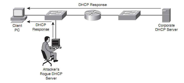
On a DHCP-enabled network, Attackers can connect their rouge DHCP server (or use hacking tools like gobbler) to perform further attack. When client broadcasts DHCP request, the DHCP response from spoofing DHCP server might assign the attacker’s IP address as client’s default gateway or DNS server. As a result, hacker can capture traffic that send from client.

The DHCP snooping feature on Cisco Catalyst switches can be used to combat a DHCP server spoofing attack. With this solution, Cisco Catalyst switch ports are configured in either the trusted or untrusted state. If a port is trusted, it is allowed to receive DHCP responses (OFFER, ACK, NAK). Converely, if a port is untrusted, it is not allowed to receive DHCP response, and if a DHCP response attemps to enter an untrusted port, the port’s then disabled.

By default, when we enable DHCP snooping feature, all ports are considered to be in untrusted state.

Configure DHCP snooping

Globally enable DHCP snooping:

Ip dhcp snooping

We can also enable DHCP snooping for specific VLANs:

Ip dhcp snooping vlan 7,10,30-40

After enable DHCP snooping, indicate the trust ports:

Interface gigaethernet 0/1
Ip dhcp snooping trust

Another type of DHCP attack is a DOS attack against DHCP server (by using hacking tools like gobbler).  Specifically, the attacker can repeatedly request IP address assignments from DHCP server with many different MAC addresses. That causes the DHCP pool be quickly full, and cannot assign IP address for clients’ legitimate requests. To mitigate such that DOS attack, DHCP snooping can be used to limit the number of DHCP messages per second:

Interface gigaethernet 0/2
Ip dhcp snooping limit rate 3

DYNAMIC ARP INSPECTION

The DHCP snooping feature dynamically builds a DHCP binding table, which contains the MAC addresses mapped to IP addresses. Additionally, this feature supports static MAC address to IP address mapping. This DHCP binding table can be used by the Dynamic ARP Inspection (DAI) feature to help prevent Address Resolution Protocol (ARP) spoofing attacks. DAI works similarly to DHCP Snooping that using trusted and untrusted ports.

ARP replies are allowed into switch on trusted port.

On untrusted port, when an ARP reply comes, it is compared to the DHCP binding table. If violence occurs, the ARP reply is dropped and the switch port is disbled.

We should run DAI on all our switches. Cisco’s recommended trusted/untrusted port configuration is to have all ports connected to hosts run as untrusted port and all ports connected to switches as trust ports.

Configure Dynamic ARP Inspection

Globally enable DAI feature:

Ip arp inspection vlan 10

Configure the DAI trusted ports:

Interface gigaethernet 0/3
ip arp inspection trust

Verify configuration:

show ip arp inspection statistics

If host uses static IP assignment:

Arp access-list static-arp
permit ip host 10.10.10.163 mac host aabb.ccdd.0011
end
Ip arp inspection filter static-arp vlan 101

IP SOURCE GUARD

IP Source Guard is a security feature that restricts IP traffic on untrusted Layer 2 ports by filtering traffic based on the DHCP snooping binding database or manually configured IP source bindings. This feature helps prevent IP spoofing attacks when a host tries to spoof and use the IP address of another host. Any IP traffic coming into the interface with a source IP address other than that assigned (via DHCP or static configuration) will be filtered out on the untrusted Layer 2 ports.

The IP Source Guard feature is enabled in combination with the DHCP snooping feature on untrusted Layer 2 interfaces. It builds and maintains an IP source binding table that is learned by DHCP snooping or manually configured (static IP source bindings). An entry in the IP source binding table contains the IP address and the associated MAC and VLAN numbers. The IP Source Guard is supported on Layer 2 ports only, including access and trunk ports.

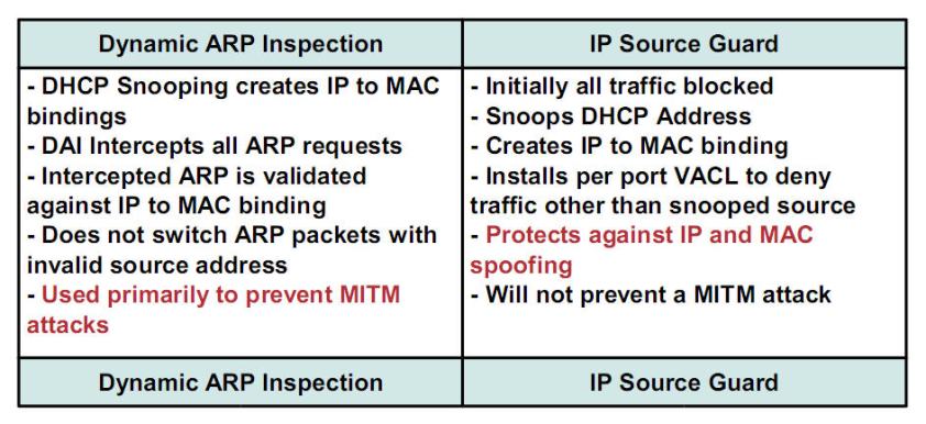
Keep in minds that IP source guard just like DAI but for IP source address (works without the attack using ARP for source address)

Here is the comparation between DAI and IP Source Guard:

Configuration example:

Interface  gigabitEthernet1/0/1
Ip verify source port-security

Learning IINS (Part 6) – L2 Security

Understanding Dot1x Port-based Authentication

What is Dot1x Port-based Authentication

IEEE 802.1x (802.1x) is a standards-based approach for providing port-based network access.

802.1x is a layer2 protocol that defines how Extensible Authentication Protocol (EAP) frames are encapsulated.

802.1x also defines hardware components, such as the figure below:

Supplicant: PCs, laptops, other devices that support 802.1x standard.

Authenticator: Catalyst Swicths, Access Points, …

Authentication Server – Radius Server: Microsoft Radius servers, Cisco secure ACS, …

Authentication Process

Let’s consider the figure below:

Step1: When boots up or pluged-in to the switch, the 802.1x-enabled PC initially sends a Extensible Authentication Protocol over LAN (EAPOL) request.

Step2: The switch that configured 802.1x receives the request and reply with a challenge.

Step3: The PC sends its credentials, such as username/password.

Step4: The Switch forwards these credentials to the authentication server – Radius server.

Step5: Radius Server validates Credentials. Upon that verification, the switch grants the PC access to the network or not.

Switch Ports Authorization state

In 802.1x environment, the  physical switch port that has the  PC connect to devides to 2 logic ports: a controlled port & an uncontrolled port.
The uncontrolled port is the only port over which PC can send traffic until it is authenticated. This uncontrolled port passes only EAPOL, CDP and STP traffic.
After the PC is authenticated, the physical switch port opens its controlled port, overwhich PC can send user data.

If the PC is configured for 802.1x but the switch is not, the PC fails to receive the EAP traffic from the switch. So the PC acts as if it has been authenticated and begin transmits its user data.
Conversely, the switch considers that the PC does not have credentials. So the switch does not grant network access to the PC.

During IEEE 802.1x authentication, depending on the switch port state, the switch can grant a client access to a network. We can control the port authorization state by using dot1x port-control interface configuration command with the keyworks:

  • Force-authorized: This is the default setting, which means that there’s no 802.1 authentication.
  • Forced-unauthorized: This option causes the switch ports to remain in the unauthorized state.
  • Auto: this is the most common setting. This option causes the switch ports to participate in 802.1x.

802.1x Host Mode

We can configure an IEEE 802.1x port for single-host mode or for multiple-hosts mode.

Single-host mode: only one client can be connected to the 802.1x-enabled switch port.

Multiple-hosts mode: multiple hosts can be connected to the 802.1x-enabled switch port. In this mode, if a single host authenticates, the port transitions to the authorized state, allowing all other hosts access to a network. We can combine 802.1x and port security to manage the network access.

Extensible Authentication Protocol

IETF said:

This document defines the Extensible Authentication Protocol (EAP), an authentication framework which supports multiple authentication methods.  EAP typically runs directly over data link layers such as Point-to-Point Protocol (PPP) or IEEE 802, without requiring IP.  EAP provides its own support for duplicate elimination and retransmission, but is reliant on lower layer ordering guarantees. Fragmentation is not supported within EAP itself; however, individual EAP methods may support this.

EAP may be used on dedicated links, as well as switched circuits, and wired as well as wireless links.  To date, EAP has been implemented with hosts and routers that connect via switched circuits or dial-up lines using PPP [RFC1661].  It has also been implemented with switches and access points using IEEE 802  IEEE-802].  EAP encapsulation on IEEE 802 wired media is described in [IEEE-802.1X], and encapsulation on IEEE wireless LANs in [IEEE-802.11i].

One of the advantages of the EAP architecture is its flexibility. EAP is used to select a specific authentication mechanism, typically after the authenticator requests more information in order to determine the specific authentication method to be used.  Rather than requiring the authenticator to be updated to support each new authentication method, EAP permits the use of a backend authentication server, which may implement some or all authentication methods, with the authenticator acting as a pass-through for some or all methods and peers.

So, EAP is not a specific authentication mechanism. It’s an authentication framework. EAP provides some common functions and negotiation of authentication methods, called EAP methods. There are about more than 40 EAP methods which are clearly defined in IETF document. Some most-used methods include EAP-MD5, Cisco LEAP, EAP-FAST, Protected EAP (PEAP), EAP-TLS.

Configure and Monitoring IEEE 802.1x

Step1. Enable AAA on Catalyst Switch

Aaa new model

Step2. Enable 802.1x Authentication

Aaa authentication dot1x default group radius local

Step3. Optionally configure Authorization

Aaa authorization network default group radius

Step4. Configure the  Switch to communicate with the Radius Server

Radius-server host 10.0.0.1
Radius-server key keyhere

Step5. Globally enable 802.1x on the Catalyst Switch

Dot1x system-auth-control
Dot1x guest-vlan supplicant (optionally configure the support of Guest Vlan )

Step6. Configure 802.1x on an Interface

Switchport mode access
Dot1x port-control auto
Dot1x host-mode multi-host
(optionally configure 802.1x to operate in multi-hosts mode)
Dot1x guest-vlan 100 (optionally configure Guest Vlan)
Dot1x auth-fail vlan 200 (optionally configure Restricted Vlan)

Step7. Verify the configuration

Show dot1x
Show dot1x fa0/1
Show dot1x statistics interface fa0/1
Show aaa servers

Learning IINS (Part 5) – L2 Security

VLAN Hoping Attack

VLAN Hopping Attack allows traffic from one  Vlan to pass into another VLAN, without first being route.

VLAN hopping can disable any security measures users may have in place on the device which maps routes between the VLAN’s. Hackers use VLAN hopping to capture sensitive information such as bank account details and passwords from targeted network subscribers. VLAN hopping is also used by some attackers to corrupt, modify, or delete data from the end user’s computer. Another intended use of VLAN hopping is to propagate viruses, worms, Trojan horses, and other malicious programs such as malware and Spyware.

Two common methods of VLAN Hopping: Switch Spoofing and Double Tagging.

Switch Spoofing

Default, Ethernet Trunks on Cisco Catalyst Switches carry traffic for all VLANs.

Come Cisco Catalyst switch ports default for auto mode for trunking, which means that ports automatically become trunk ports if they receive Dynamic Trunking Protocol (DTP) frames.

Attackers could attemp to make the victim’s switch to enter trunking mode either by spoofing DTP frames (tools like Yersinia) or by connect with a real switch.

Mitigation:

a. Disable Trunking on all ports that do not need to form trunks:

Interface  ethernet 0/1
Switch port mode access
Exit

b. Prevent the use of DTP:

Interface ethernet 0/2
Switchport trunk encapsulation dot1q
Switchport mode trunk
Switchport nonegotiate

Double Tagging

Keep in mind that On an IEEE 802.1Q Trunk (Only on dot1q trunk), the native VLAN does not add any tagging to frames travelling from one switch to another switch.

If an attacker ‘s PC belongs to the native VLAN, he could exploit this native VLAN characteristic to send traffic that has two 802.1Q Tags. The outer tag is for the native VLAN, the inner tag is for the target VLAN to which the attacker want to inject traffic.

As illustrated in Figure below, SW1 removes the outer tag (specifies the native VLAN) from frame before forwarding the frame to SW2. When receive the frame, SW2 “sees” only inner tag (VLAN100) and SW2 sends the traffic out to the target VLAN.

Mitigation:

To help prevent a VLAN hopping attack using double tagging, do not use the native VLAN to send users’ traffic. This cound accomplished by creating a VLAN that does not  have any ports. This unused VLAN is solely for the perpose of native VLAN assignment.

Interface gigaethernet 0/3
Switchport trunk native vlan 400

Learning IINS (part 4) – L2 Security

CAM overflow attacks

  • CAM – Content Addressable Memory
  • Switch = Hub + CAM
  • CAM table is built based-on Source Mac Address
  • CAM table is not infinite in size
  • CAM Overflow Attack  ~  Mac flooding attack (tool as macof): Attacker floods a single port on the switch with a lot of frames that contain different source mac addresses. The CAM table be quickly full & Switch works like a HUB (fail-over mode). At this time, attacker can sniffer all network traffic.

Mitigation

We can use Port-security feature to mitigation this type of attack.

  • Enable Port-security:

Switchport mode access (*only applicable to access ports – NOT trunks*)

Switchport port-security (*per interface*)

  • Set maximum number of MAC Addresses that Switch can be learned on a port:

Switchport port-security maximum 3

  • Set violation mode for the port:

Switchport port-security violation {protect | restrict | shutdown | shutdown vlan}

protect silently drops

restrict drops and sends notification via SNMP trap or

syslog messages

shutdown shutdown the port (error-disabled state), changes the led state and send notification

shutdown vlan 5 same as shutdown, but only applys to the specific VLAN

  • Set static mac-addresses to allow:

Switchport port-security mac-address abcd.efgh.1234

  • Enable sticky learning of secure MAC addresses on a port:

Switchport port-security mac-address sticky

“Sticky secure MAC addresses—These are dynamically configured, stored in the address table, and added to the running configuration. If these addresses are saved in the configuration file, when the switch restarts, the interface does not need to dynamically reconfigure them.”

  • Configure Aging for secure MAC addresses:

Switchport port-security aging {static | time| type}

  • Verify configuration:
    • Show port-security
    • Show port-security address
    • Show port-security int fa0/1

Learning IINS (part 3)

Configure Router to use external AAA Servers

There are 3 main steps to remember:

Task1: configure AAA network (make AAA client *routers here*  and AAA servers *tacacs+ and/or radius* to communicate)

Task2: setup users (on AAA server)

Task3: Configure AAA and where to be applied

——————————————————————

Examples configuration on Router:

Aaa new-model

Tacacs-server host 10.0.0.1 key 3Akey


Aaa authentication login AAA_example group tacacs+ local
Aaa authorization exec group tacacs+
Aaa authorization network tacacs+
Aaa accounting connection default start-stop group tacacs+

Line vty 0 4
Login authentication AAA_example
Accounting connection default

Learning IINS (part 2)

Configure Authentication with Local Database AAA on a Cisco Router

Keep in mind that there are 5 basic steps to configure Local Database AAA on a Cisco Router. Here is the 5 steps and examples commands:

Task 1: Create local user

Username Admin1 privilege 15 secret admin123

Task 2: Enable AAA on the router

AAA new-model

Task 3: Configure AAA on the router. Define what type of remote access (administrative – telnet, ssh, http or network – PPP, Dial-in,…) AAA is to be performed

Aaa authentication login default local
Aaa authentication ppp dial-in local

Task 4: Apply authentication list to Router lines or Network

Line vty 0 4
Login authentication default

Int se0/0
Ppp authentication chap dial-in

Tank 5: Verify AAA configuration

Debug aaa authentication
Terminal Monitor

Show aaa user all

Show aaa sessions

More Local Database AAA commands:

Lockout user after 7 times login attemps failed:

Aaa local authentication attemps max-fail 7

Display locked-out users:

Show aaa local user lockout

Clear (re-active) all locked-out users:

Clear aaa local user lockout

Clear specific user (User1 in this example):

Clear aaa local user lockout User1

Learning IINS (part 1)

Securing Administrative Access to Cisco Routers

Some basic commands to secure administrative access to cisco Routers.

* Set password enable

Enable Secret or
Enable Password

* Console Terminal

Line console 0
Login
Password Enablepa55
Exec-timeout 2 30
Loggin synchronous

* Virtual Terninal

Line vty 0 4
Login
Password VTYpa55
Exec-timeout 2 30
Loggin synchronous

* Auxiliary line

Line console 0
Login
Password Auxpa55
Exec-timeout 2 30
Loggin synchronous

* Enable Password Encryption

Service password-encryption

* Enable Password Policy

Security passwords min-length 6

*  Secure ROMMON mode

No service password-recovery (Be careful with this command !)

* Setting multiple privilege levels

Eg:

Privilege exec level 5 ping
Enable secret level 5 operatorpa55
(to login using command: enable 5)

* Configure Role-based Access to CLI

Enable AAA:                               
aaa
new-model

Set enable password:
enable secret enablepa55

Switch to view mode:             
enable view

Create a view:
parser view Operator Secret operatorpa55
commands exec include ping
commands exec include show hardware
commands exec include show interface
commands exec include show ver

Add a view to user:
username operator view operator secret operatorpa55

Login to view
enable view operator

* Configuring the Cisco IOS Resilient configuration feature

Protect IOS Image:                 
Secure boot-image

Protect NVRAM:                     
Secure boot-config

Show secured copies:
Show secure bootset

* Create a Banner Message

Banner Motd | Incoming | Exec | Login | SLIP-PPP

* Enable Cisco IOS Login Enhencements for virtual connections (HTTP, TELNET, SSH)

Login block for 120 attemps 10 within 30

Allow subnet 10.0.0.0/24 to login to Router during Quiet Period:
Access-list Admin_Access_Always permit 10.0.0.0 0.0.0.255
Login quiet-mode access-class Admin_Access_Always

Delay between login attempts:
Login delay 1

Logging:
Login on-success log
Login on-failure log

Show login